A few years ago I bought a Taig Tools milling machine:


I find that there are a number of small projects that I would like to do that I don't really want to fire up a full CAD program to create, or that are more easily created procedurally, but that are also too complicated to write directly in gcode. To address this I've written a scripting program based on the Delphi version of the Pascal language that allows me to quickly create gcode output with some backplotting capabilities.
The application is currently in a functional proof-of-principle format, and so only supports a few built-in operations, such as slots and circle pockets. As I work with it these capabilities will be expanded so that most common operations will be easily accomplished. Don't hold your breath though, without a CNC machine at my disposal I'm not in a big hurry to work on this application.
When writing a script to output gcode it is useful to see a preview of the toolpath that will be generated. To this end I've included an OpenGL based 3D toolpath viewer. This allows the user to display a rectangular workpiece and the lines that describe the path of the tip of the tool. It does not currently create a simulation of the part that will be cut, nor does it indicate where the edges of the bit would be.
Since gcode generated from a script like this can be quite large I've compiled the script engine into a DOS program that can run on a DOS computer with a program like TurboCNC or CNCPro. This application can be used to edit, compile and run the scripts, and it can be used from a batch file with a script name as a parameter to generate gcode.
In the future I would like to improve the backplotter to make it a general purpose tool, so that it can take any gcode and display the tool path it generates, which will facilitate a number of functions of the program, most specificly the import of existing gcode files.
The application and example script files may be downloaded. If you try the application, please let me know what you think of it.
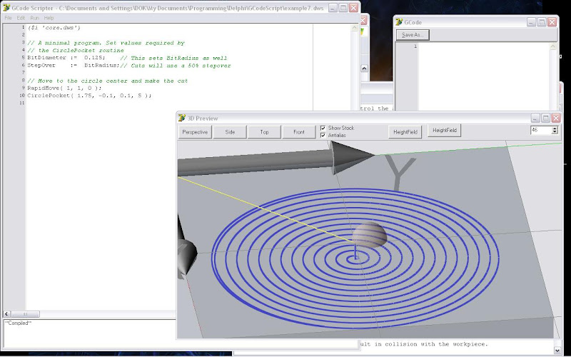
This is a very basic program to cut a circle pocket. The script code sets a couple of values required by the circle pocket routine, rapids to the desired location, then calls the circle pocket routine. At the bottom of the code window you can see that the code has been compiled. When the code is run with the 'simulation' flag on it generates the 3D graphical output you can see at the bottom right.
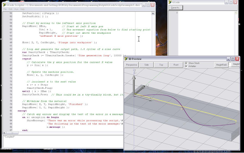
This is one of the example scripts that comes with the application. It calculates a simple path using the sin function. The code for the script is more complex and takes advantage of more language features. You can see use of some of the built in variables (X, Y and Z), the 'repeat...until' loop, creation of a helper object (the TSanityCheck object) and exception handling (if an error occurs it will generally create an exception that ends up in the 'except' block). In the 'except' block you can see a call to the ShowMessage() routine which will display the error message on screen.
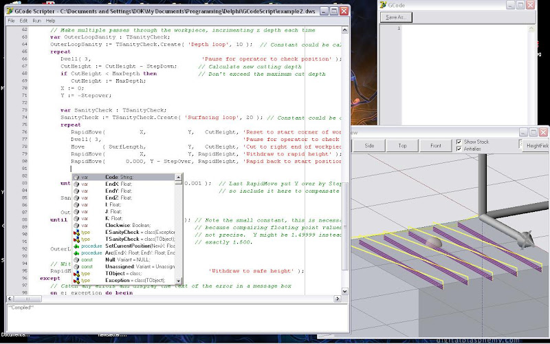
Here we see example script 2 which is used to face off a block. The user specifies in the script the dimensions of the block, the depth of each pass and the max depth and the script generates the necessary gcode. In the script window the use has pressed the Alt+Space hotkey to bring up the code insight window so he can look up available variables, classes and functions. This feature makes recalling and entering the names of functions and variables very easy.
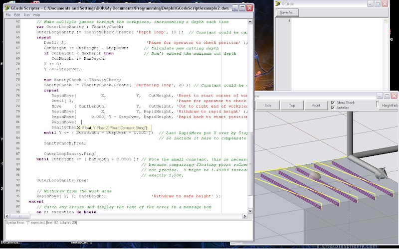
This is the same as the previous example, but displaying the parameter insight window. This feature displays on screen the parameters required for any given function. In this case the user has selected the RapidMove() function and you can see the X, Y, Z and Comment parameters with their associated types. Note that the Comment parameter is in brackets. This indicates that the parameter is optional and can be omitted if the user prefers.
This is from example script 5, a script that will generate the code required to cut successive circle pockets into a cube to create a nested cube object. The parameter insight feature is displaying the parameters for the circle pocket function.
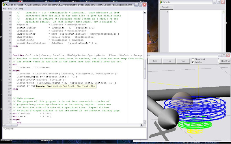
The nested cube object looks like this:

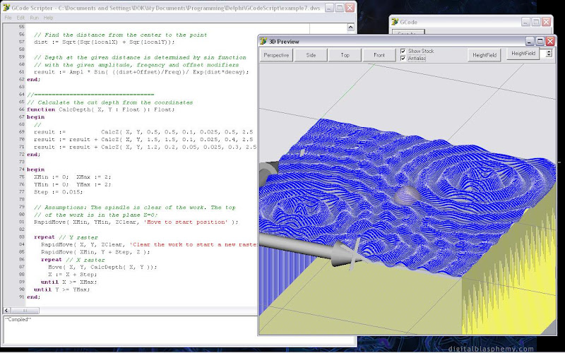
This example program uses a couple of subroutines to calculate the amplitude of a sine function that is defined at three locations on the working plane. These routines are used to calculate the Z depth as raster lines are traced across the face of the block. In the example I have set the rapid height to be negative (deep into the block) so that the cut lines can be seen more easily. The resolution of the figure can be adjusted very easily by increasing or decreasing the value of the 'Step' variable. As written the script does not automatically make multiple passes to reach a target depth, the figure must be cut in a single pass.
Finally, this is the simple script from the first example running in the new DOS script engine. The DOS application runs the same script engine as the windows version and so is able to run the same scripts to generate the same output. I'm still working on the user interface on this application (the Turbo Vision version I'm using has a few bugs to work out), but the script core is all working and is happy to run all the same scripts as the windows version, although it will ignore the graphical commands and does not include the code and parameter insight features.
