This entry is simply a collection of notes about the Itron Remote Read Electric Meter protocol. Since I'm getting to the point with my AVR Butterfly where I will need to start feeding it actual meter data I need to know more about the data format. So here are the interesting bits I'm finding.
These notes are from a patent assigned to EnScan, and may or may not be relevant to the Itron meter.
The transponder signal is comprised of a series of eight spaced transmission bursts, or transponder information packets.
Each transponder information packet is separated in time from adjacent transponder information packets by a predetermined period S.
Each transponder information packet is transmitted at a pseudorandom frequency ranging from 912 MHz to 918 MHz.
Each transponder information packet within a single transponder signal is identical.
Transponder information packets are divided into a plurality of data fields including preamble field, spare field, instrument type field, instrument parameter field, tamper field, instrument identification field and error control code field.
The transmission of each transponder information packet begins with preamble data field with bit sequence 111110010101001100000 which provides bit sync and word sync for digital decoders within the receiver.
The spare data field follows the preamble field and is five bits in length and is reserved for future use.
The instrument type field follows the spare bit field and is four bits in length. It contains data representative of the particular type of instrument with which transponder is associated.
The instrument parameter field follows instrument type field and is twenty-two bits in length. It contains data representative of the parameter sensed by meter
The tamper field follows instrument parameter field. It is a four bit field and contains data representative of tampering.
The instrument identification field follows tamper field, and is twenty-four bits long. It contains data identifying the particular meter with which the transponder is associated.
Transponder information packets end with the 16 bit error control code field the contents of which is produced as a function of the data contained in the spare, instrument type, instrument parameter, tamper, and instrument identification data.
The BCH encoder produces a BCH error control code constructed of a shortened 255, 239, 2 code Galois field generated by the following polynomial: P(X)=1+X+X5 +X6 +X8 +X9 +X10 +X11 +X13 +X14 +X16.
The Manchester encoder implements a Manchester I encoding scheme. Manchester encoders are well known and produce a code in which a data clock is embedded into the data stream.
The Manchester encoded bit stream forming the transponder information packet is used to on-off key (OOK) the carrier signal.
The sequence timing control is unresponsive to enable signals from the enable circuit for 10 seconds after transmission of a final transponder information packet of transponder signal. If after this predetermined "dead time" period the transponder receives another activation signal, the sequence timing control will initiate transmission of another transponder signal.
Patent for a system that reads meters for an in-home display:
http://www.freepatentsonline.com/7427927.html
Another:
http://www.freepatentsonline.com/7209840.html
http://www.freepatentsonline.com/7427927.html
Wednesday, December 17, 2008
Thursday, December 4, 2008
Arduino on the AVR Butterfly
When I started my Itron meter reader project I had to get the AVR Butterfly up and running under AVR Studio. This was a little tedious but eventually I got it working. While I was doing that I thought that it would be useful to be able to run Arduino code on the Butterfly. I looked around a bit and found that there was a thread on the Arduino.cc forum about doing just this.
I went on with AVR Studio, but just the other day user Nick Lott posted some of the groundwork that sets up the Arduino IDE to work with the butterfly. After a bit of poking around with it to get the clock frequency and USART set up properly, it's working great. The AnalogInput sample even reads the light sensor and writes to the piezo speaker out of the box (the brighter the light, the faster it ticks).
I made the following changes.
Edit boards.txt to update to 8Mhz:
bfly.build.f_cpu=8000000L
This didn't seem to have any effect so I edited the butterfly\makefile to update to 8Mhz:
F_CPU = 8000000
Update 2009-Jan-30
I have written (or adapted code for) several classes to handle the Butterfly's hardware. The LCD, temp sensor, dataflash chip, and RTC clock all have easy-to-use interfaces now. The LCD class could be better, it needs some error checking and doesn't integrate with the Print class as nicely as it could, but it's quite functional.
The project is up on Google Code, feel free to check it out.
Monday, October 6, 2008
The AVR Butterfly as a Data Logger
I was browsing some messages in the Arduino forum today and I ran across
this great Butterfly data logger project.
It gives some neat examples of using the $25 Butterfly board (for $45 you can get it on a PCB breadboard with all the goodies already attached, great deal).
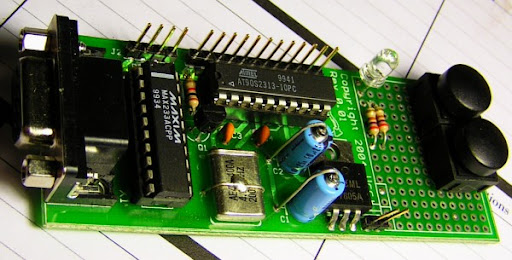
I'm using the butterfly as the basis for developing my Itron meter reader. I'll do the development on the butterfly, then transfer the program to one of the 2313 boards I developed a few years ago:
this great Butterfly data logger project.
It gives some neat examples of using the $25 Butterfly board (for $45 you can get it on a PCB breadboard with all the goodies already attached, great deal).
I'm using the butterfly as the basis for developing my Itron meter reader. I'll do the development on the butterfly, then transfer the program to one of the 2313 boards I developed a few years ago:
It's pretty chunky, but it's got the power supply and serial port and a place to put the RF board, it should be perfect. It's also got some space that I could stick some I2C flash memory onto for data logging. The 2313 is a pretty limited device, it won't be able to log data for very long with out some off-chip memory.
I've mounted the butterfly onto the back of a 2 D cell battery and affixed it with a bit of ShapeLock. I soldered on some headers to let me connect to the ports and made a serial cable from an old mouse cord (also using ShapeLock).
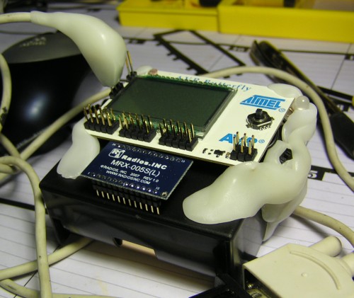
I've mounted the butterfly onto the back of a 2 D cell battery and affixed it with a bit of ShapeLock. I soldered on some headers to let me connect to the ports and made a serial cable from an old mouse cord (also using ShapeLock).
It looks a bit crappy, but it doesn't fall apart, and the other board looks nice. :)
Next step is to write a program that will read the output of the RF board and send it to the computer via the serial port. Once I get a look at the waveform I can make some decisions about how to decode it on the AVR.
Update 2008-Dec-3
I've spent quite a few hours over the past few weeks working with the Butterfly and AVR Studio to try to get it to do what I want. Since this is the first time I've worked with Mega processors it has been a bit of a learning process. I spent a couple of weeks working on the software and finally got really stuck, so I took a break for a week and came back to it last night. Almost immediately I corrected the problems and now have it reading the output of the RF board from a wireless temperature monitor (there's another post around here somewhere about that monitor).
I am using what I suspect is a pretty inefficient method to read the data stream, but it's working. I've configured the Butterfly's Mega169 Timer1 to trigger an interrupt every 100uS which updates a system timer counter. The pin change interrupt is set up to watch for changes on the joystick pins and to set a variable to idenfity which button changed and whether it is up or down. This information is made availble through a 'keypressed' funtion. In the main loop I read the keypressed function until I get a valid input, then I read the timer value and the button state (up or down) , reset the timer, then write the string-formatted timer value and button position out to the serial port (which runs at 115200).
This is all built on the GCC port of the Butterfly source code with some minor adjustments and additions from the AVRFreaks board (a new, faster and more flexible OSCCAL_Calibrate function, for example). In order to make it easier to learn what I'm doing I tried to stick with the basic archetecture of the Butterfly code. That's got it working, but the way I'm using the timer is really pretty dumb. It's easy to understand though, and it works, so for the time being I'm going to leave it. If I do move this down to the 2313 I'll have to be much smarter about resource usage, I don't think the 2313 at 4Mhz would handle this very well.
The datastream going to the computer is currently being read by a simple C# app that uses ZedGraph to display the live data stream. It normalizes the bit widths for display and seems to do a pretty reasonable job of making the data visible. Next I need to set it up to log the data so I can save to a file for analysis.
If I was going to continue with the temperature monitors I'd spend some time analysing the bitstream and compairing it to the transmitted temperature. From what I've seen it transmits the data packet four times and each transmission consists of about 16 bits (maybe 20, I'm not sure if the last four are data bits or framing). The temperture range is something like -22°F to 122°F, or -29°C to 50°C, a range of about 79°C or 142°F. It includes a tenth degree figure as well, but I'm not sure if that digit has a resolution of 0.1 or 0.2.
Regardless, the project is not to read the temperature data (although that would be interesting too), but to read the datastream from the Itron meter. Fortunately the datastream format for that is documented, so there won't be any time-consuming reverse-engineering there.
At this point the next step is to get the 800Mhz RF receiver set up to see if I can read the data coming from the meter. I'll have to rig up something to connect to the header pins on it, they're closer than 0.1" spacing of common headers and I don't have anything that connects to them.
Here's a picture of the bitstream from the temp monitor. Each of the '1's are 0.5mS.

Friday, May 23, 2008
Yaesu FT-8800 Button Mod
I recently purchased an Yaesu FT-8800R 144/430 MHz dual band FM transceiver. I wanted the dual radio feature which makes it easy to operate on one channel while checking other things on the other channel. It is two identical radios in one box.
The two complaints I have about the radio so far are that the interface buttons are all very small, which makes operating the radio while driving a little difficult, and that the tiny buttons are not backlit, which makes finding them at night next to impossible. You have to feel around on the front of the radio and hope you don't bump the 'set' button in the middle or whack either of the volume or squelch controls too hard.
I took the radio faceplate apart and found that the buttons have lots of space around them. They are suspended in a little plastic collar that allows them to float in the bezel with a gap about 1mm wide around the sides of the button. While I'm sure this gap will allow all kinds of dust into the workings, it also means any light shining behind the buttons will leak out around them.
I immediately grabbed some tools and started making. The first step was to see if the LEDs I had handy would fit:

You can see the first set of 4 LEDs on the right, they will shine through the little hole above the button support. It would probably be best to paint the area under the buttons white so the light shows up as much as possible.
Here is a closer look at one of the LEDs and the PCB material I'm using:

After some work with some 600 grit sandpaper the bit of PCB just fits:

I was in a bit of a rush to get this project done so rather than setting up to etch the board I simply filed a slot through the copper. I know, lazy, but it would have taken longer to go microwave the etchant than do this. Etching would reduce the thickness of the light bar by eliminating the wire that I had to use for this installation.

Here I've started installing the LEDs. I do this by melting a thin layer of solder over where the LED will sit, then carefully placing the device. When I've got it in the right place I use the iron to melt the solder which lightly tacks down the device. I can then press it down with a finger without knocking it out of alignment and get a proper amount of solder on it.
The power connector is just a 12v automotive power adapter that I cut
in half and connected to the header and insulated with some heat shrink
tubing.
I wanted to use red LEDs to go with the amber faceplate, but I could not find any until I was finished. I may go ahead and make a second version using the red LEDs. This time I'll try putting them under the buttons instead of above.
Here is a blurry picture of the result. Obviously you cannot read the captions on the buttons, but I don't really need to, the text is so small I can't usually read it while I'm driving anyway. The point is to make the buttons visible without requiring a lamp or having to feel around in the dark. This meets the requirement nicely I think.

The two complaints I have about the radio so far are that the interface buttons are all very small, which makes operating the radio while driving a little difficult, and that the tiny buttons are not backlit, which makes finding them at night next to impossible. You have to feel around on the front of the radio and hope you don't bump the 'set' button in the middle or whack either of the volume or squelch controls too hard.
I took the radio faceplate apart and found that the buttons have lots of space around them. They are suspended in a little plastic collar that allows them to float in the bezel with a gap about 1mm wide around the sides of the button. While I'm sure this gap will allow all kinds of dust into the workings, it also means any light shining behind the buttons will leak out around them.
I immediately grabbed some tools and started making. The first step was to see if the LEDs I had handy would fit:
You can see the first set of 4 LEDs on the right, they will shine through the little hole above the button support. It would probably be best to paint the area under the buttons white so the light shows up as much as possible.
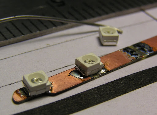
Here is a closer look at one of the LEDs and the PCB material I'm using:
You can get a sense of the size of both from the millimeter scale on the ruler next to it. A smaller LED would be better, as LEDs go this one is pretty chunky and it does complicate the installation a bit. It also has contacts all the way across the bottom which requires me to install a wire for the power rather than etching it into the PCB. Double sided PCB would take care of that, but I didn't happen to have any.
Here I've cut off a piece of the board just wide enough to fit between the button posts and the edge of the display. At the ends I've trimmed it a little bit to allow for the end buttons which are placed just a bit higher than the rest.

Here I've cut off a piece of the board just wide enough to fit between the button posts and the edge of the display. At the ends I've trimmed it a little bit to allow for the end buttons which are placed just a bit higher than the rest.
You can see how the board must be trimmed up to fit over the last buttons:

I was in a bit of a rush to get this project done so rather than setting up to etch the board I simply filed a slot through the copper. I know, lazy, but it would have taken longer to go microwave the etchant than do this. Etching would reduce the thickness of the light bar by eliminating the wire that I had to use for this installation.
Here I've started installing the LEDs. I do this by melting a thin layer of solder over where the LED will sit, then carefully placing the device. When I've got it in the right place I use the iron to melt the solder which lightly tacks down the device. I can then press it down with a finger without knocking it out of alignment and get a proper amount of solder on it.
Now I've got all 8 LEDs installed. The first one there is a little wonky, but it's close enough for a prototype. The sets of LEDs are on 10mm centers, but the two banks are offset from each other by about 0.5mm. I'm not using any resistors for this project. The docs for the LEDs say they work great without a resistor from about 2.5 to 4 volts, so I'm just going to do 2 banks of 4 in series.

Speaking of power, there has to be a way to power this thing, and I'm not sure what the power budget of the faceplate is, nor do I particularly want to start mucking about with the electronics in this thing yet, it's only a week old after all. So, rather than taking any such risk I went ahead with modifying the case. I loaded the faceplate onto the drill press and poked a few holes in it, then finished it with a file.

This is sized to hold the female part of a 2 pin header. They carry more than enough power and are small enough to be installed without making too much of a mess of the case.

Speaking of power, there has to be a way to power this thing, and I'm not sure what the power budget of the faceplate is, nor do I particularly want to start mucking about with the electronics in this thing yet, it's only a week old after all. So, rather than taking any such risk I went ahead with modifying the case. I loaded the faceplate onto the drill press and poked a few holes in it, then finished it with a file.
This is sized to hold the female part of a 2 pin header. They carry more than enough power and are small enough to be installed without making too much of a mess of the case.
I'm using some magnet wire as hookup wire. Again, very lazy, a proper installation would use wire-wrap wire or something else with proper insulation. You can see here that I'm installing the negative lead in the middle of the light bar. Ideally you'd use double-sided board and just put a via here to connect to a negative trace on the back of the board, then run that over to the end where the power leads connect. As I mentioned before this would reduce the thickness of the board by the diameter of the wire as it eliminates the requirement to run a wire all the way down to the other other end of the board.
I ran the wires around the knob on the right side of the faceplate and replaced the bit of black stuff that goes around the screen. Take care not to touch the clear screen cover or the LCD itself. It's much easier to keep them clean than it is to get them clean again. Also, the LCD seems to be particularly sensitive to touch and I suspect it would be easy to damage.

I ran the wires around the knob on the right side of the faceplate and replaced the bit of black stuff that goes around the screen. Take care not to touch the clear screen cover or the LCD itself. It's much easier to keep them clean than it is to get them clean again. Also, the LCD seems to be particularly sensitive to touch and I suspect it would be easy to damage.
At this point I'm ready to connect the power connector and epoxy it in. Here it is read to accept the the epoxy:


Most of the epoxy goes inside to secure the connector, but some goes in the hole to make it look a bit better. Honestly, I can do better work than this, but it was pushing 5AM at this point and I just wanted to get done. I still had to be at work at 8, and I figured I could use a couple hours of sleep at least.
in half and connected to the header and insulated with some heat shrink
tubing.
I wanted to use red LEDs to go with the amber faceplate, but I could not find any until I was finished. I may go ahead and make a second version using the red LEDs. This time I'll try putting them under the buttons instead of above.
Here is a blurry picture of the result. Obviously you cannot read the captions on the buttons, but I don't really need to, the text is so small I can't usually read it while I'm driving anyway. The point is to make the buttons visible without requiring a lamp or having to feel around in the dark. This meets the requirement nicely I think.
You can see that the right-most button is not well lit. I think the LED over there is offset a little too much and doesn't shine through the little hole over the button very well. It is brighter than it looks here, but it is dim enough to be visually unappealing.
The biggest problem is that the thickness of the light bar restricts the movement of the buttons a bit which makes it hard to push a few of them. In particular the scan button on the right is very stiff. Functionally this isn't a problem because with some effort they do work and I can use the soft buttons on the mic (which also aren't lit!) to access all of those functions. It is annoying though, and it offends my sense of proper workmanship.
I consider this a failed project because it reduces the quality of some elements of the original project. I believe though that the idea is good and that I can product another version that will work as intended. And it'll be red instead of blue.
I think that a better way to do this modification would be to remove the buttons and fabricate a new set using clear plastic. This would allow for proper back-lighting as found on some of Yaesu's other radios. If I could get a spare face plate to work with I'd be willing to develop the buttons necessary to do this, but Yaesu's website doesn't list a price for a replacement faceplate.
Tuesday, February 5, 2008
Itron Remote Read Electric Meter
My house is equipped with an Itron remote read electric meter. This is a fancy digital electric utility meter that broadcasts it's usage information so the meter guys can just drive around to get usage information for billing. I'd like to track my usage but there isn't an easy way to read the meter electronically, since it is digital it does not have one of those spinning wheels with the index mark on it, just an array of 7 segment LCD numbers and three little dots flashing at the bottom. The dots indicate usage, but are too far under the protective glass housing to read optically (well, they could be read that way, but I'm trying to avoid it). It also has an IR LED that flashes once for each watt-hour consumed. See below for more details on that.
Most of the below is from some research I did a year ago and posted to Mark Turner's blog. I'm republishing it here so I know I can find it again.
I’ve been doing some research on the meter in an attempt to avoid having to install a cheap wireless camera over the meter to OCR the images :D.
Itron makes a number of EMT modules for AMR purposes and I’m guessing that they all use pretty much the same protocol (that makes it easier to sell more stuff and easier to develop new products for the same line). The modules can be integrated with old style meters to retrofit AMR capability to old equipment or it can be installed as a plug-in module to electronic meters (and of course Itron sells their own meters as well, I’ve got the Centron CS1R model). The CS1R/R300 IDM meters presumably either use the 5xESS ERT modules or a built-in version of the same thing. Thus a utility using, e.g. GE meters with 52ESS ERT modules could also buy Centron CS1R meters from Itron and use all the same remote-read equipment.
The literature all touts the Spread Spectrum radio feature, and that generally means some flavor of frequency hopping where bits or chips of the message are transmitted across multiple frequencies and the entire message is not available on any one frequency. Itron seems to keep this information secret though, so their competitors don’t set up to read it (except where the FTC forced them to give a license to Neptune as a anti-anti-competitive measure).
Update: It isn't secret, US Patent 4,799,059 has all the details.
The thing is, I don’t think they are doing anything particularly fancy to get that spread spectrum label. The primary consideration is not security (anybody can walk up to the meter, and its just utility usage data anyway) but reliability. AMR technology is there to save money, and hard-to-read meters cost more. Also, I suspect the ’spread spectrum’ is in the sales literature to look fancy and sound impressive, not to tell us they are using a fancy PN frequency hopping routine to secure the information.
Here are some bits I’ve scrounged up:
“The ERT meter module can be programmed to communicate in either wake-up or bubble-up mode. When used in wake-up mode, it waits for a wake-up signal over a radio frequency and then automatically transmits the meter data to the appropriate meter-reading device. In bubble-up mode, a constant stream of data is transmitted for interception, by the receiving unit, and no FCC license is required. This data includes the meter ID number, registration, and tamper detection information. The RF transmission lasts less than one second and contains eight identical data packets, each at a different frequency. The modules can be read by DataCommand, DataPac and Mobile Collection Systems as well as the G5R handheld and the fixed base MicroNetwork.”
“When programming the 53ESS ERT, customers [utility companies] can select any three payloads from the available list. The 53ESS ERT transmits this data back to the Itron meter reading software via three standard consumption messages (SCMs). Each SCM contains a payload data value, an ERT ID, and counters providing tamper and/or other meter related information.”
“Two counters in each of the SCMs provide a total of six unique status indicators that provide important information about site conditions, including detection of possible tampering.
SCM1 Counter1 Meter has been inverted
SCM1 Counter2 Meter has been removed
SCM2 Counter3 Meter detected a button–press demand reset
SCM2 Counter4 Meter has a low-battery/end–of–calendar warning
SCM3 Counter5 Meter has an error or a warning that can affect billing
SCM3 Counter6 Meter has a warning that may or may not require a site visit, depending on utility practice (for example, reverse energy flow warning)”
One of the important tidbits there is this “The RF transmission lasts less than one second and contains eight identical data packets, each at a different frequency.”
It sounds to me like they are transmitting the exact same, complete message on 8 independent frequencies spread across the spectrum (thus, “spread spectrum” in the sales literature). I would not be surprised at all if this is really just 8 redundant OOK broadcasts at different frequencies. This would be consistent with the two driving principles, avoiding interference and keeping the cost low.
Update: According to the patent this seems to be correct:
The data sounds like it consists of 3 SCM messages, each containing bits representing the payload, the ERT and the counters. The payload for each SCM is configurable. The 3 SCM’s comprise a single data packet and are transmitted in under one second, probably with at least (IIRC) 15 seconds between them (in compliance with FCC Part 15 sub C).
In bubble-up (1 way) mode you’d receive the broadcasts constantly. In wake-up (also referred to as 1.5 way) mode the reader has to chirp some kind of wake up message to get the meter to broadcast. I didn’t find any information about the reader’s wake up broadcast, but there might be some clues in the FCC’s documentation:
EO9DCPN2 Meter Reading Transmitter
EWQ90F2482517-410 Meter Reader/Programmer
EWQ90F2482517E Utility Meter Transceiver
EWQ90F6482517-R Utility Meter Transceiver
If it is confirmed that the meter is transmitting a basic OOK/FSK message as I suspect, it shouldn’t be a huge leap to work out the signaling protocol (probably also a standard scheme). Determining how the checksum works could be more difficult, but for stationary monitoring I can get a way without it. They might also ‘encrypt’ the data, but since we know the KWH used at the time of transmission at least that part of the data should be recoverable (presuming a simple scrambling system).
Update: The CRC is also published:
Here is an index of some relevant patents:
http://www.patentstorm.us/assignees/Itron,_Inc_-52765-1.html
This one is very relevant:
“Communication Protocol for remote data generating stations”
http://www.patentstorm.us/patents/5673252-description.html
In particular the description of the Network Service Module (NSM) is useful.
Also “Frequency Hopping Spread Spectrum system with high sensitivity tracking and syncronization”, which describes the details of how the SS system works:
http://www.patentstorm.us/patents/6934316-description.html
I haven’t finished reading it all, but what I understand is that the receiver starts out in a wideband receive mode to pick out the transmitter’s preamble. Evidently the transmitter and receiver don’t have a predetermined channel hopping pattern, the transmitter hops around however it wishes and the receiver does it’s best to find the signal. When the first part (34 chips of Manchester coded bitstream) of the preamble is found an FFT is run to cut the 7Mhz spectrum into 32 channels which it watches for the remaining 6 chips. These chips show up most strongly in one of the channels, or bins, identifying the narrowband frequency the transmitter is using. The receiver then tunes and syncs a narrowband receiver to that frequency to pick up the packet data. If the signal strength is high enough to receive the data in wideband mode it doesn’t bother switching to narrowband mode.
I think that part is particularly interesting. Because I'm interested in reading only one nearby meter I can ignore the whole frequency hopping part and use a wideband receiver with low selectivity. Since each packet is transmitted 8 times across the spectrum the band doesn’t even have to be very wide, I’ll be likely to pick up enough data with a simple receiver, even if some of the packets and broadcasts are missed.
Some information about the mode used:
Other Itron patents describe the data content of the packets and the length (about 100mS, 8 of which then take “under one second”). So, I think this project can be done without too much trouble.
I confirmed with the Itron rep that works with my power company that my meter operates in bubble-up mode, so I know that the data is there, I just need to set up a receiver to look for it.
This document says that the 53ESS ERT operates in the 900MHz band:
And I found this, which should be helpful in decoding the data, in a WIPO document:
An MRX-005 or MRX-505 might be used to pick it up. It receives at 915MHz. Since the transmitter sends 8 copies of the data, randomly distributed across the 912-918 MHz band, at least one of the transmissions should be easily within the bandwidth of the receiver (that's the point of sending it 8 times, after all). At $14 (receiver) or $25 (transceiver) they are cheap enough to try out.
Just for grins I set up my FT-8800 to scan the band from 912 to 913MHz. I set the squelch well above the background noise and listened for a while. It did occasionally pick up something and stop, but the transmissions are too short to catch. Scanning sections above 930MHz didn't turn up any noise, so it could be that it was picking up the SCM transmissions.
Update : 2008-09-22
I ordered the MRX-005S from Digikey on Friday and it arrived today, Monday. This is a nice all-in-one OOK receiver. It operates from 902-928 MHz and the ERT should be transmitting, as above, between 912 and 918 MHz.

It's simple enough to power up and doesn't require any tuning, so hopefully I can stick the scope on it and take it out to the meter and see if I can pick up some data. If that works it'll just be a matter of piping the data into an AVR, then sending it out the com port to the computer for decoding.
I also found in the documentation that the meter has a simple IR port on it that flashes once per watt-hour, much like the little three dot display on the front. This would be useful for a simple power usage monitor where the usage numbers where not important. For example this indicator could be used as the input to a rate display located somewhere in the house. On example of this that I've read about as a possibility would be a wall sconce that glows green below a certain usage rate and then fades up through various shades until it gets to red above a certain rate. Another option might be vernier-type display. Such display systems would provide immediate and constant feedback for occupants who could then become more aware of how their actions caused power consumption to increase or decrease.
The IR port is located on the top of the meter:

As usual with IR LEDs, you can see the IR light with a CCD, such as a video camera. The flashes are very brief though, so they don't show up very brightly on the video:
The camera frame rate is not synchronized/locked with the led, so it's likely that the video doesn't catch all the flashes or even all of the individual flashes. However, it appears to get most of them as the rate in the video matches pretty close to what was displayed on the front of the meter at the time.
Update 2008-10-1
I dug out my Atmel Butterfly and started setting it up for this project. I bought it a couple years ago and never got around to doing anything with it. Since my STK200 development kit is so old now most of the current development tools don't support it easily. Since I like things to be easy I'm going to see if I can get the Butterfly working as a development platform instead. Once I get the code all working I'll transfer it to one of my older chips, or maybe to anArduino Mini, those are popular and I'd like to play with one.
Update 2009-Jan-20
Well, getting out the Butterfly has kind of set this project back. I ended up getting sidetracked onto making the Butterfly work with the Arduino IDE (see the Butteruino on Google Code). This has ended up sucking up a great many hours. At this point it's working fairly well but could use some more work to pretty it up. I'm going to try to switch back to this project now.
The next step is to see if I can get Timer2 on the Butterfly set up to read the input data from the RF module. Even running at the Butterfly's max clock of 8MHz doesn't leave a lot of time to process the incoming bitstream. It looks like it won't be a problem, but there won't be a lot of time to waste. It's tempting to move up to a 20MHz device, but I suppose I should keep it cheap so I can put it on one of my 2313's.
Update 2009-Jun-20
I've found that I like working with Arduino, so I recently put together a couple of iDuino boards. These are Arduino-compatible boards with a Mega168 running at 16MHz and an onboard FT232 for USB to RS-232 conversion. They are just under an inch wide and have downward-facing headers so they can be plugged into a solderless breadboard. I really like this board, I'd certainly recommend it if you prototype on solderless breadboard and use Arduino.
I was somewhat annoyed to find that the MRX-005 module's pins are not on 1/10 inch centers, so it cannot be plugged directly into a breadboard. Fortunately, while it has a lot of pins only a few actually need to be connected. I have it inverted on my breadboard, dead-bug style, with jumpers wrapped around the legs.

Yeah, it's a messy hack, but it's just a prototype. I attached a few feet of antenna and was able to capture some data.

The transitions aren't as sharp as I'd like to see, but it should easily be clean enough to decode.
I've also writen some C# code for parsing data samples from the OpenAMR project into graphable data. Hopefully the data from my Itron meter will be the same as that data. My library is smart enough to handle different kinds of data input, but I don't want to have to figure out what the fields in this data are.
Next step is to do some research about how to go about decoding this Manchester encoded bitstream on the AVR. I could invent something, but that would be dumb, this wheel has been invented many times.
Update 2009-July-7
I've made a bit more progress over the last couple of weeks. The next step was to impliment an Manchester decoder on the Arduino. I poked around on the Arduino site a bit, but didn't find anything immediately useful. Greg Hancock's brief OpenAMR page on Manchester coding mentions that he is using the scheme that happens to be published in US Patent 5,200,980 "Digital Bi-Phase Data Recovery System" by Dennis M. Briddell. That sounded like a good place to start, so I implemented it in an Arduino sketch (I'll move it to a library once it is all debugged).
While testing I found that the radio module doesn't output a clean logic signal, instead it provides an analog mess which doesn't work very well with the edge triggered interrupt on the AVR. I thought it would be good to clean it up by running it through a Schmitt trigger, but I don't have any and I don't want to pay shipping on only a few chips. It turns out that you can configure a 555 as an inverting Schmitt triggered buffer with no external parts, and it's easily fast enough to handle the 30uS signals from the meter datastream.
For testing purposes I assembled a second iDuino board and set it up to output some test data in Manchester format (sending it sure is a lot easier than receiving it!). The receiver appears to mostly work with the simple test data packets I'm sending, but I get occasional glitches. Even if I can't work those out it won't be much of an issue since the AMR data is retransmitted many times.
I think for the next step I will improve the code on the second iDuino to provide more realistic sample data. Currently the data rate is much lower (1mS chips instead of 30uS) and the data frames are only 4 bytes. I'll use some of the 92 byte sample data from the OpenAMR project, that should let me prove out the decoding routines without the unknown factors in the data from the radio module. Once I've got that working I'll switch back to the radio module and see if I can decode some actual data.
Update 2012-July-12
Here is the above-mentioned sample of the AMR data, in image format. See the comments below for C# code that defines the field layout.
 I haven't been doing anything much with this project over the past few years (lots of other stuff going on, including building up the Omaha Maker Group), but I recently obtained one of the new RTL-SDR USB devices that I thought might make this project really easy. I'll see if I can get some data captures with it.
Update 2014-July-17
The RTL-SDR captures the AMR broadcasts very nicely. I placed the antenna directly on top of the transmitter and captured a few transmissions. It's also easy to see broadcasts from other meters in the vicinity.

Recording the incoming data to a wav file produces about what you'd expect:

Looks just like the scope trace. I'm using SDRSharp which supports plugins, so I'm going to look into writing a decoder plugin. The option to record and reply signals with SDRSharp will make debugging quite a bit simpler.
Most of the below is from some research I did a year ago and posted to Mark Turner's blog. I'm republishing it here so I know I can find it again.
I’ve been doing some research on the meter in an attempt to avoid having to install a cheap wireless camera over the meter to OCR the images :D.
Itron makes a number of EMT modules for AMR purposes and I’m guessing that they all use pretty much the same protocol (that makes it easier to sell more stuff and easier to develop new products for the same line). The modules can be integrated with old style meters to retrofit AMR capability to old equipment or it can be installed as a plug-in module to electronic meters (and of course Itron sells their own meters as well, I’ve got the Centron CS1R model). The CS1R/R300 IDM meters presumably either use the 5xESS ERT modules or a built-in version of the same thing. Thus a utility using, e.g. GE meters with 52ESS ERT modules could also buy Centron CS1R meters from Itron and use all the same remote-read equipment.
The literature all touts the Spread Spectrum radio feature, and that generally means some flavor of frequency hopping where bits or chips of the message are transmitted across multiple frequencies and the entire message is not available on any one frequency. Itron seems to keep this information secret though, so their competitors don’t set up to read it (except where the FTC forced them to give a license to Neptune as a anti-anti-competitive measure).
Update: It isn't secret, US Patent 4,799,059 has all the details.
The thing is, I don’t think they are doing anything particularly fancy to get that spread spectrum label. The primary consideration is not security (anybody can walk up to the meter, and its just utility usage data anyway) but reliability. AMR technology is there to save money, and hard-to-read meters cost more. Also, I suspect the ’spread spectrum’ is in the sales literature to look fancy and sound impressive, not to tell us they are using a fancy PN frequency hopping routine to secure the information.
Here are some bits I’ve scrounged up:
“The ERT meter module can be programmed to communicate in either wake-up or bubble-up mode. When used in wake-up mode, it waits for a wake-up signal over a radio frequency and then automatically transmits the meter data to the appropriate meter-reading device. In bubble-up mode, a constant stream of data is transmitted for interception, by the receiving unit, and no FCC license is required. This data includes the meter ID number, registration, and tamper detection information. The RF transmission lasts less than one second and contains eight identical data packets, each at a different frequency. The modules can be read by DataCommand, DataPac and Mobile Collection Systems as well as the G5R handheld and the fixed base MicroNetwork.”
“When programming the 53ESS ERT, customers [utility companies] can select any three payloads from the available list. The 53ESS ERT transmits this data back to the Itron meter reading software via three standard consumption messages (SCMs). Each SCM contains a payload data value, an ERT ID, and counters providing tamper and/or other meter related information.”
“Two counters in each of the SCMs provide a total of six unique status indicators that provide important information about site conditions, including detection of possible tampering.
SCM1 Counter1 Meter has been inverted
SCM1 Counter2 Meter has been removed
SCM2 Counter3 Meter detected a button–press demand reset
SCM2 Counter4 Meter has a low-battery/end–of–calendar warning
SCM3 Counter5 Meter has an error or a warning that can affect billing
SCM3 Counter6 Meter has a warning that may or may not require a site visit, depending on utility practice (for example, reverse energy flow warning)”
One of the important tidbits there is this “The RF transmission lasts less than one second and contains eight identical data packets, each at a different frequency.”
It sounds to me like they are transmitting the exact same, complete message on 8 independent frequencies spread across the spectrum (thus, “spread spectrum” in the sales literature). I would not be surprised at all if this is really just 8 redundant OOK broadcasts at different frequencies. This would be consistent with the two driving principles, avoiding interference and keeping the cost low.
Update: According to the patent this seems to be correct:
the Manchester encoded bit stream forming transponder information packet 42 is used to on-off key (OOK) the carrier signal.
Each transponder information packet 42 of transponder signal 40 is
transmitted at a pseudorandom frequency (i.e., a pseudorandom carrier
frequency) within a predetermined range of frequencies. In one
embodiment, transponder information packets 42 are transmitted at
frequencies ranging from 912 MHz to 918 MHz.
The data sounds like it consists of 3 SCM messages, each containing bits representing the payload, the ERT and the counters. The payload for each SCM is configurable. The 3 SCM’s comprise a single data packet and are transmitted in under one second, probably with at least (IIRC) 15 seconds between them (in compliance with FCC Part 15 sub C).
In bubble-up (1 way) mode you’d receive the broadcasts constantly. In wake-up (also referred to as 1.5 way) mode the reader has to chirp some kind of wake up message to get the meter to broadcast. I didn’t find any information about the reader’s wake up broadcast, but there might be some clues in the FCC’s documentation:
EO9DCPN2 Meter Reading Transmitter
EWQ90F2482517-410 Meter Reader/Programmer
EWQ90F2482517E Utility Meter Transceiver
EWQ90F6482517-R Utility Meter Transceiver
If it is confirmed that the meter is transmitting a basic OOK/FSK message as I suspect, it shouldn’t be a huge leap to work out the signaling protocol (probably also a standard scheme). Determining how the checksum works could be more difficult, but for stationary monitoring I can get a way without it. They might also ‘encrypt’ the data, but since we know the KWH used at the time of transmission at least that part of the data should be recoverable (presuming a simple scrambling system).
Update: The CRC is also published:
In one preferred embodiment, BCH encoder 104 produces a BCH errorI’ve emailed both my power company and Itron about reading the meter myself. Both were very friendly. The Basic DOS-based meter reader is available if you want to buy it, but at a bit over 5 kilobucks it’s not a viable solution (unless you can get your utility company to sell you any broken readers at a substantial discount).
control code constructed of a shortened 255, 239, 2 code Galois field
generated by the following polynomial: P(X)=1+X+X 5 +X 6 +X 8 +X 9 +X 10 +X 11 +X 13 +X 14 +X 16 .
Here is an index of some relevant patents:
http://www.patentstorm.us/assignees/Itron,_Inc_-52765-1.html
This one is very relevant:
“Communication Protocol for remote data generating stations”
http://www.patentstorm.us/patents/5673252-description.html
In particular the description of the Network Service Module (NSM) is useful.
Also “Frequency Hopping Spread Spectrum system with high sensitivity tracking and syncronization”, which describes the details of how the SS system works:
http://www.patentstorm.us/patents/6934316-description.html
I haven’t finished reading it all, but what I understand is that the receiver starts out in a wideband receive mode to pick out the transmitter’s preamble. Evidently the transmitter and receiver don’t have a predetermined channel hopping pattern, the transmitter hops around however it wishes and the receiver does it’s best to find the signal. When the first part (34 chips of Manchester coded bitstream) of the preamble is found an FFT is run to cut the 7Mhz spectrum into 32 channels which it watches for the remaining 6 chips. These chips show up most strongly in one of the channels, or bins, identifying the narrowband frequency the transmitter is using. The receiver then tunes and syncs a narrowband receiver to that frequency to pick up the packet data. If the signal strength is high enough to receive the data in wideband mode it doesn’t bother switching to narrowband mode.
I think that part is particularly interesting. Because I'm interested in reading only one nearby meter I can ignore the whole frequency hopping part and use a wideband receiver with low selectivity. Since each packet is transmitted 8 times across the spectrum the band doesn’t even have to be very wide, I’ll be likely to pick up enough data with a simple receiver, even if some of the packets and broadcasts are missed.
Some information about the mode used:
- The transmitter uses Manchester coding: “the preamble 32 of the packet 30 consists of 20 bits plus one sync bit. This data is Manchester encoded so we have 42 “chips” (i.e. transition states) possible to correlate on. The first 34 chips are used to correlate on and the last 6 to determine the best bin for data decoding.”
- The narrowband data is OOK : “In a preferred embodiment, the encoded data of the packet 30 is on-off keyed (OOK) modulated.”
- Eight duplicate packets are sent, each entirely on a single channel: “A typical end point transmitter will respond to a valid wake-up with eight packets, which will be sent at slightly different frequencies”
- The wake-up tone, if it is used, is a simple flag signal and encodes no data: “end-point modules, even those that normally operate in a bubble-up fashion, respond to a wake-up tone, which is a proper frequency carrier modulated at the programmed wake-up tone.”
- “end point transmitters provide the capability to select a wide range of wake-up frequencies (952-956 MHz) and wake-up tones (28-62 Hz)”
Other Itron patents describe the data content of the packets and the length (about 100mS, 8 of which then take “under one second”). So, I think this project can be done without too much trouble.
I confirmed with the Itron rep that works with my power company that my meter operates in bubble-up mode, so I know that the data is there, I just need to set up a receiver to look for it.
This document says that the 53ESS ERT operates in the 900MHz band:
53ESS ERT Specifications:
• Transmit frequency: 910 MHz to 920 MHz
And I found this, which should be helpful in decoding the data, in a WIPO document:
An example of a SCM format is illustrated in FIG. 3 A. e.g., 21 -bit preamble field followed by 2 ID bits, 1 spare bit, 2 physical tamper bits, 4 endpoint type bits, 2 encoder tamper bits, 24 consumption data bits, 24 ID bits, 16 CRC checksum bits (this can also be found in U.S. Patent No. 4,799,059, which describes the ERT packet in detail)
An MRX-005 or MRX-505 might be used to pick it up. It receives at 915MHz. Since the transmitter sends 8 copies of the data, randomly distributed across the 912-918 MHz band, at least one of the transmissions should be easily within the bandwidth of the receiver (that's the point of sending it 8 times, after all). At $14 (receiver) or $25 (transceiver) they are cheap enough to try out.
Just for grins I set up my FT-8800 to scan the band from 912 to 913MHz. I set the squelch well above the background noise and listened for a while. It did occasionally pick up something and stop, but the transmissions are too short to catch. Scanning sections above 930MHz didn't turn up any noise, so it could be that it was picking up the SCM transmissions.
Update : 2008-09-22
I ordered the MRX-005S from Digikey on Friday and it arrived today, Monday. This is a nice all-in-one OOK receiver. It operates from 902-928 MHz and the ERT should be transmitting, as above, between 912 and 918 MHz.

It's simple enough to power up and doesn't require any tuning, so hopefully I can stick the scope on it and take it out to the meter and see if I can pick up some data. If that works it'll just be a matter of piping the data into an AVR, then sending it out the com port to the computer for decoding.
I also found in the documentation that the meter has a simple IR port on it that flashes once per watt-hour, much like the little three dot display on the front. This would be useful for a simple power usage monitor where the usage numbers where not important. For example this indicator could be used as the input to a rate display located somewhere in the house. On example of this that I've read about as a possibility would be a wall sconce that glows green below a certain usage rate and then fades up through various shades until it gets to red above a certain rate. Another option might be vernier-type display. Such display systems would provide immediate and constant feedback for occupants who could then become more aware of how their actions caused power consumption to increase or decrease.
The IR port is located on the top of the meter:

As usual with IR LEDs, you can see the IR light with a CCD, such as a video camera. The flashes are very brief though, so they don't show up very brightly on the video:
The camera frame rate is not synchronized/locked with the led, so it's likely that the video doesn't catch all the flashes or even all of the individual flashes. However, it appears to get most of them as the rate in the video matches pretty close to what was displayed on the front of the meter at the time.
Update 2008-10-1
I dug out my Atmel Butterfly and started setting it up for this project. I bought it a couple years ago and never got around to doing anything with it. Since my STK200 development kit is so old now most of the current development tools don't support it easily. Since I like things to be easy I'm going to see if I can get the Butterfly working as a development platform instead. Once I get the code all working I'll transfer it to one of my older chips, or maybe to anArduino Mini, those are popular and I'd like to play with one.
Update 2009-Jan-20
Well, getting out the Butterfly has kind of set this project back. I ended up getting sidetracked onto making the Butterfly work with the Arduino IDE (see the Butteruino on Google Code). This has ended up sucking up a great many hours. At this point it's working fairly well but could use some more work to pretty it up. I'm going to try to switch back to this project now.
The next step is to see if I can get Timer2 on the Butterfly set up to read the input data from the RF module. Even running at the Butterfly's max clock of 8MHz doesn't leave a lot of time to process the incoming bitstream. It looks like it won't be a problem, but there won't be a lot of time to waste. It's tempting to move up to a 20MHz device, but I suppose I should keep it cheap so I can put it on one of my 2313's.
Update 2009-Jun-20
I've found that I like working with Arduino, so I recently put together a couple of iDuino boards. These are Arduino-compatible boards with a Mega168 running at 16MHz and an onboard FT232 for USB to RS-232 conversion. They are just under an inch wide and have downward-facing headers so they can be plugged into a solderless breadboard. I really like this board, I'd certainly recommend it if you prototype on solderless breadboard and use Arduino.
I was somewhat annoyed to find that the MRX-005 module's pins are not on 1/10 inch centers, so it cannot be plugged directly into a breadboard. Fortunately, while it has a lot of pins only a few actually need to be connected. I have it inverted on my breadboard, dead-bug style, with jumpers wrapped around the legs.
Yeah, it's a messy hack, but it's just a prototype. I attached a few feet of antenna and was able to capture some data.
The transitions aren't as sharp as I'd like to see, but it should easily be clean enough to decode.
I've also writen some C# code for parsing data samples from the OpenAMR project into graphable data. Hopefully the data from my Itron meter will be the same as that data. My library is smart enough to handle different kinds of data input, but I don't want to have to figure out what the fields in this data are.
Next step is to do some research about how to go about decoding this Manchester encoded bitstream on the AVR. I could invent something, but that would be dumb, this wheel has been invented many times.
Update 2009-July-7
I've made a bit more progress over the last couple of weeks. The next step was to impliment an Manchester decoder on the Arduino. I poked around on the Arduino site a bit, but didn't find anything immediately useful. Greg Hancock's brief OpenAMR page on Manchester coding mentions that he is using the scheme that happens to be published in US Patent 5,200,980 "Digital Bi-Phase Data Recovery System" by Dennis M. Briddell. That sounded like a good place to start, so I implemented it in an Arduino sketch (I'll move it to a library once it is all debugged).
While testing I found that the radio module doesn't output a clean logic signal, instead it provides an analog mess which doesn't work very well with the edge triggered interrupt on the AVR. I thought it would be good to clean it up by running it through a Schmitt trigger, but I don't have any and I don't want to pay shipping on only a few chips. It turns out that you can configure a 555 as an inverting Schmitt triggered buffer with no external parts, and it's easily fast enough to handle the 30uS signals from the meter datastream.
For testing purposes I assembled a second iDuino board and set it up to output some test data in Manchester format (sending it sure is a lot easier than receiving it!). The receiver appears to mostly work with the simple test data packets I'm sending, but I get occasional glitches. Even if I can't work those out it won't be much of an issue since the AMR data is retransmitted many times.
I think for the next step I will improve the code on the second iDuino to provide more realistic sample data. Currently the data rate is much lower (1mS chips instead of 30uS) and the data frames are only 4 bytes. I'll use some of the 92 byte sample data from the OpenAMR project, that should let me prove out the decoding routines without the unknown factors in the data from the radio module. Once I've got that working I'll switch back to the radio module and see if I can decode some actual data.
Update 2012-July-12
Here is the above-mentioned sample of the AMR data, in image format. See the comments below for C# code that defines the field layout.

Update 2014-July-17
The RTL-SDR captures the AMR broadcasts very nicely. I placed the antenna directly on top of the transmitter and captured a few transmissions. It's also easy to see broadcasts from other meters in the vicinity.
Recording the incoming data to a wav file produces about what you'd expect:
Looks just like the scope trace. I'm using SDRSharp which supports plugins, so I'm going to look into writing a decoder plugin. The option to record and reply signals with SDRSharp will make debugging quite a bit simpler.
Thursday, January 17, 2008
A Simple Binary Clock Project
In about April of 2004 I started this binary clock project which was inspired by the Think Geek binary clock. I put the project on hold a number of times and finally finished it around October of 20032004. When I started the project the TG clock was only available with red LEDs, and while it was definitely pretty cool, there were a number of things about it that bothered me. Obviously it needed blue LEDs, which are all the rage for the modern appliances. It also displays the time in 6 binary registers, one each for the 6 decimal digits of a digital clock. While this arrangement generates some pretty gnarly patterns, and is probably why it was chosen, it seemed very un-geekish to me. Lastly, and most importantly, since one of the guys I work with already had a red TG binary clock on his desk, if I was to have one, it couldn't be the same design, and it would have to somehow out-geek that other clock.
Clearly I would have to create my own binary clock from scratch to meet my requirements. As the only 'crossover geek' in the office (programming and hobby-level digital electronics), I could meet the primary goal of out-geeking the existing clock with my own AVR microcontroller based design.
Since presentation is important as well I choose to use a dead harddrive as the case for the clock. This presented some
interesting challenges, as there isn't really much room inside a hard drive. I considered using surface mount parts as I have
with other projects, but eventually decided against it. I don't like making PCBs for SMT parts as I don't have a well refined technique for etching boards, the fine features associated with SMT parts don't come out well and sometimes cause frustration and SMT parts don't fit well on the perf board I thought would look suitably homemade. While I could have a PCB made for the surface mount parts, it could end up looking more professional than I wanted. I wanted this thing be reasonably good looking, but I also wanted it to look home-built.
Rather than use 6 binary registers for a 6 digit display, I choose to go with two 6 bit registers, one each for seconds and minutes, and one 5 bit register for hours (I prefer the 24 hour time format, so support for that was required). This loses some cool points when it comes to the fascinating patterns that the Think Geek clock generates, but I think it is easier to read, more elegant, and, importantly, different.
I briefly considered keeping the HD platters on the motor and mounting some SMT LEDs so I could create a radial matrix display, but the difficulty of working with the moving parts required for that design added a level of commitment that I wasn't prepared to deal with (it took about 6 months to finally get it done as it was!). I still think it's a cool idea, and I've seen a number of such 'propeller' or 'persistence of vision' as they are called now, clocks. Perhaps I'll do something like it in the future. Since I made this clock 'persistence of vision' displays have become pretty common (see MAKE magazine), so doing it now shouldn't be too difficult.
I decided to use the Atmel AT90S2313 for this project. It is a 20 pin, 8 bit, 2kb flash-based RISC controller with built-in
UART. It's small, and has plenty of I/O for this task, and I've got a pile of them that aren't doing anything but taking up space and taunting me for not using them. The code is written in C, and compiled with the AVRGCC compiler. Since I do not use C I'm sure the quality of the code is abysmal. I referred to the K&R book quite often while writing the code you see below. It's been so long since I wrote it that I really don't recall what the heck I was thinking when I invented it, and most of the coding sessions where late-night Git'er Done sessions, so it is highly likely that there is some pretty whacked out code in there. Normally I'd take a lot more care in designing it, but by the time I got to the software I just wanted to get the darn thing finished.
The 3 registers are arranged around the platter in two horizontal and one vertical row. The seconds register is laid out horizontally at the bottom of the platter with the LSB on the right, minutes is vertically oriented on the right, LSB at the bottom, and hours is parallel to seconds at the top. Since the hours register is one bit shorter, the right-most position is not drilled out. I had actually intended to leave the left-most position undrilled, but I'm a goober and soldered the LEDs in wrong. After the difficulty I had wiring them up to the right angle headers with magnet wire (a horrible choice of material, I should have waited and picked up some more suitable wire at the local electronics supply store, but I was overeager to get it running. That decision cost me many hours of tedious wiring and troubleshooting), I wasn't inclined to change them.

I built three small boards to go on the back of the HDD case, onto which the LEDs are mounted, one board for each register. The boards contain 5 or 6 LEDs, an 6 pin single row 90 degree header, and a darlington PNP transistor and base resistor. The header pins are for power, enable and 5 or 6 LED ground wires. The PNP is controlled by the enable line, which is connected to the base via the resistor. When on it provides current to the LEDs. The ground lines are switched on the main board by a row of NPN transistors to turn on or off each LED.
I didn't have the Taig CNC milling machine at the time, so I used a hand drill and some files to make the openings in the back of the disk drive. The aluminum used for the case is very soft and cuts beautifully, if the mill had been available I would have considered doing some more interesting work on the exposed metal areas. I also would have etched something onto the platters I used for the face (I also would have had neatly aligned holes for the LEDs instead of the slightly wonky holes it has now).

The cables from the three boards run to a concentration point, also on the back of the drive. This wires together all the LED
ground wires and power, and brings the three column enable lines into the cable which runs through the existing access hole in the back of the clock to connect to the main board. I liberally applied hot glue to keep everything in place.

On the main board is a row of NPN transistors and their resistors, 3 buttons for setting the time, and the microcontroller itself, along with a few supporting parts. The NPN's are the other side of the control of the current to the LEDs, they work with the PNP's on the LED boards to control the current to each individual LED. There are other ways to control banked arrays of LEDs that can save IO lines, but you don't save much with this small number of LEDs, and I didn't have any shortage of IO lines.
To provide a nice look, I was pretty set against showing the tops of the LEDs. While the lenses are water clear, they will
always look like LEDs, which, while certainty geeky, isn't very pretty. I located some 1/4 inch clear lexan rod that I found
would carry the light very nicely, like an optical fiber. I cut it into pieces about 3/8ths of an inch long and frosted both
ends (chuck the rod into the drill and apply fine sandpaper) to diffuse the light from the LEDs. By mounting the bits of rod with about an 1/8th inch sticking out above the polished drive platter, I got a very nice modern look. The frosted end of the rod glows bright blue, but the sides are clear, with very little light leakage. The effect is of an intense blue disk hovering over the mirrored surface.
I dislike the very abrupt on-off nature of the Think Geek binary clock LEDs, the sudden changes catch my attention when the clock is at the edge of my field of view. It was apparent that this would not be acceptable for something that would be sitting on my desk all day. I used an ugly hack in the software to adjust the pulse width of the signal sent to each LED that was changing states. Each transition has a 1/4 second linear ramp to full on or off, which makes it look much more serene, and eliminates the snap of the TG clock.
Unfortunately, I've set the scan rate such that under just the right conditions I can see the flicker of the LEDs when they
are ramping on or off, but its very minor. Someone with very 'fast' vision might be more irritated by it. I can see and am annoyed by CRTs set for a 60Hz refresh rate, and the flicker of fluorescent lights and movie screens often bothers
me but not most others, so perhaps I'm just picky.
Overall the clock turned out pretty nice, although it has lots of room for improvement in all aspects. The software could be
much more elegant and extensible, the hardware has a number of dumb design elements, and the fit and finish could use plenty of work. In particular the hardware needs a microprocessor supervisor chip and battery backup, and it should be using a crystal that lends itself to more accurate timekeeping. The 4MHz crystal I used does the job acceptably, but choosing constant values for calculating the time in the software is dodgy. It also drifts with the temperature more than it ought to, a more stable crystal would be nice.
If I do another version I will include a Real Time Clock chip to handle the timekeeping, including battery backup. I can then
use the microcontroller to run a speaker for alarms and timers (1 hour 'lunch timer' and 5 minute tea timers would be handy, as well as an 'its 5pm, go home' notifier). I'd also like to include USB support to allow the clock to draw power and accurate time sync data from the computer.
The code is under the GPL, and the hardware is too trivial to be anything but public domain. Feel free to use the software under the terms of the GPL, and do whatever you wish with the hardware designs.
You can see video of the clock. The frame rate and shutter speed make the LEDs look like they pulsate a bit in the video. In person the fade is smooth and seamless.
Here is the code for the project:
Clearly I would have to create my own binary clock from scratch to meet my requirements. As the only 'crossover geek' in the office (programming and hobby-level digital electronics), I could meet the primary goal of out-geeking the existing clock with my own AVR microcontroller based design.
Since presentation is important as well I choose to use a dead harddrive as the case for the clock. This presented some
interesting challenges, as there isn't really much room inside a hard drive. I considered using surface mount parts as I have
with other projects, but eventually decided against it. I don't like making PCBs for SMT parts as I don't have a well refined technique for etching boards, the fine features associated with SMT parts don't come out well and sometimes cause frustration and SMT parts don't fit well on the perf board I thought would look suitably homemade. While I could have a PCB made for the surface mount parts, it could end up looking more professional than I wanted. I wanted this thing be reasonably good looking, but I also wanted it to look home-built.
Rather than use 6 binary registers for a 6 digit display, I choose to go with two 6 bit registers, one each for seconds and minutes, and one 5 bit register for hours (I prefer the 24 hour time format, so support for that was required). This loses some cool points when it comes to the fascinating patterns that the Think Geek clock generates, but I think it is easier to read, more elegant, and, importantly, different.
I briefly considered keeping the HD platters on the motor and mounting some SMT LEDs so I could create a radial matrix display, but the difficulty of working with the moving parts required for that design added a level of commitment that I wasn't prepared to deal with (it took about 6 months to finally get it done as it was!). I still think it's a cool idea, and I've seen a number of such 'propeller' or 'persistence of vision' as they are called now, clocks. Perhaps I'll do something like it in the future. Since I made this clock 'persistence of vision' displays have become pretty common (see MAKE magazine), so doing it now shouldn't be too difficult.
I decided to use the Atmel AT90S2313 for this project. It is a 20 pin, 8 bit, 2kb flash-based RISC controller with built-in
UART. It's small, and has plenty of I/O for this task, and I've got a pile of them that aren't doing anything but taking up space and taunting me for not using them. The code is written in C, and compiled with the AVRGCC compiler. Since I do not use C I'm sure the quality of the code is abysmal. I referred to the K&R book quite often while writing the code you see below. It's been so long since I wrote it that I really don't recall what the heck I was thinking when I invented it, and most of the coding sessions where late-night Git'er Done sessions, so it is highly likely that there is some pretty whacked out code in there. Normally I'd take a lot more care in designing it, but by the time I got to the software I just wanted to get the darn thing finished.
The 3 registers are arranged around the platter in two horizontal and one vertical row. The seconds register is laid out horizontally at the bottom of the platter with the LSB on the right, minutes is vertically oriented on the right, LSB at the bottom, and hours is parallel to seconds at the top. Since the hours register is one bit shorter, the right-most position is not drilled out. I had actually intended to leave the left-most position undrilled, but I'm a goober and soldered the LEDs in wrong. After the difficulty I had wiring them up to the right angle headers with magnet wire (a horrible choice of material, I should have waited and picked up some more suitable wire at the local electronics supply store, but I was overeager to get it running. That decision cost me many hours of tedious wiring and troubleshooting), I wasn't inclined to change them.
I built three small boards to go on the back of the HDD case, onto which the LEDs are mounted, one board for each register. The boards contain 5 or 6 LEDs, an 6 pin single row 90 degree header, and a darlington PNP transistor and base resistor. The header pins are for power, enable and 5 or 6 LED ground wires. The PNP is controlled by the enable line, which is connected to the base via the resistor. When on it provides current to the LEDs. The ground lines are switched on the main board by a row of NPN transistors to turn on or off each LED.
I didn't have the Taig CNC milling machine at the time, so I used a hand drill and some files to make the openings in the back of the disk drive. The aluminum used for the case is very soft and cuts beautifully, if the mill had been available I would have considered doing some more interesting work on the exposed metal areas. I also would have etched something onto the platters I used for the face (I also would have had neatly aligned holes for the LEDs instead of the slightly wonky holes it has now).
The cables from the three boards run to a concentration point, also on the back of the drive. This wires together all the LED
ground wires and power, and brings the three column enable lines into the cable which runs through the existing access hole in the back of the clock to connect to the main board. I liberally applied hot glue to keep everything in place.
On the main board is a row of NPN transistors and their resistors, 3 buttons for setting the time, and the microcontroller itself, along with a few supporting parts. The NPN's are the other side of the control of the current to the LEDs, they work with the PNP's on the LED boards to control the current to each individual LED. There are other ways to control banked arrays of LEDs that can save IO lines, but you don't save much with this small number of LEDs, and I didn't have any shortage of IO lines.
To provide a nice look, I was pretty set against showing the tops of the LEDs. While the lenses are water clear, they will
always look like LEDs, which, while certainty geeky, isn't very pretty. I located some 1/4 inch clear lexan rod that I found
would carry the light very nicely, like an optical fiber. I cut it into pieces about 3/8ths of an inch long and frosted both
ends (chuck the rod into the drill and apply fine sandpaper) to diffuse the light from the LEDs. By mounting the bits of rod with about an 1/8th inch sticking out above the polished drive platter, I got a very nice modern look. The frosted end of the rod glows bright blue, but the sides are clear, with very little light leakage. The effect is of an intense blue disk hovering over the mirrored surface.
I dislike the very abrupt on-off nature of the Think Geek binary clock LEDs, the sudden changes catch my attention when the clock is at the edge of my field of view. It was apparent that this would not be acceptable for something that would be sitting on my desk all day. I used an ugly hack in the software to adjust the pulse width of the signal sent to each LED that was changing states. Each transition has a 1/4 second linear ramp to full on or off, which makes it look much more serene, and eliminates the snap of the TG clock.
Unfortunately, I've set the scan rate such that under just the right conditions I can see the flicker of the LEDs when they
are ramping on or off, but its very minor. Someone with very 'fast' vision might be more irritated by it. I can see and am annoyed by CRTs set for a 60Hz refresh rate, and the flicker of fluorescent lights and movie screens often bothers
me but not most others, so perhaps I'm just picky.
Overall the clock turned out pretty nice, although it has lots of room for improvement in all aspects. The software could be
much more elegant and extensible, the hardware has a number of dumb design elements, and the fit and finish could use plenty of work. In particular the hardware needs a microprocessor supervisor chip and battery backup, and it should be using a crystal that lends itself to more accurate timekeeping. The 4MHz crystal I used does the job acceptably, but choosing constant values for calculating the time in the software is dodgy. It also drifts with the temperature more than it ought to, a more stable crystal would be nice.
If I do another version I will include a Real Time Clock chip to handle the timekeeping, including battery backup. I can then
use the microcontroller to run a speaker for alarms and timers (1 hour 'lunch timer' and 5 minute tea timers would be handy, as well as an 'its 5pm, go home' notifier). I'd also like to include USB support to allow the clock to draw power and accurate time sync data from the computer.
The code is under the GPL, and the hardware is too trivial to be anything but public domain. Feel free to use the software under the terms of the GPL, and do whatever you wish with the hardware designs.
You can see video of the clock. The frame rate and shutter speed make the LEDs look like they pulsate a bit in the video. In person the fade is smooth and seamless.
Here is the code for the project:
#include <avr/io.h>
#include <avr/interrupt.h>
#include <avr/signal.h>
#include <avr/delay.h>
#define F_CPU 4000000 /* 4Mhz */
#define UART_BAUD_RATE 9600 /* 9600 baud */
#define COLUMN_DWELL 5000
#define BTN_SET_TIME _BV(4)
#define BTN_SET_HOURS _BV(3)
#define BTN_SET_MINUTES _BV(2)
#define UART_BAUD_SELECT (F_CPU/(UART_BAUD_RATE*16l)-1)
typedef unsigned char u08;
typedef char s08;
typedef unsigned short u16;
typedef short s16;
/* uart globals */
static volatile u08 *uart_data_ptr;
static volatile u08 uart_counter;
static volatile u08 received_byte;
static volatile u08 seconds;
static volatile u08 minutes;
static volatile u08 hours;
static volatile u08 old_seconds;
static volatile u08 old_minutes;
static volatile u08 old_hours;
static volatile u16 fade_step;
static volatile u08 btn_inc_hours; // hour set button pressed, inc hour value
static volatile u08 btn_inc_minutes; // min set button pressed, inc min value
enum { SECONDS, MINUTES, HOURS };
void uart_send_byte( u08 val ){
uart_counter = 1;
UDR = val;
for (;;){
if (uart_counter == 0)
break;
}
}
SIGNAL(SIG_UART_TRANS)
/* signal handler for uart txd ready interrupt */
{
uart_data_ptr++;
if (--uart_counter)
UDR = *uart_data_ptr;
}
SIGNAL(SIG_UART_RECV){
/* signal handler for receive complete interrupt */
received_byte = UDR;
}
void inc_time(u08 time_type){
switch (time_type){
case SECONDS:
if(++seconds > 59) seconds = 0;
break;
case MINUTES:
if(++minutes > 59) minutes = 0;
break;
case HOURS:
if(++hours > 23) hours = 0;
break;
}
}
SIGNAL(SIG_OUTPUT_COMPARE1A){
// Don't update the time if the set time button is down
if ((~PIND & BTN_SET_TIME) == BTN_SET_TIME) return;
// Store the old values for cross-fading
old_seconds = seconds;
old_minutes = minutes;
old_hours = hours;
// 4992 is close to COLUMN_DWELL and allows for 13 integral steps
fade_step = 4992;
// overflow each into the next
inc_time(SECONDS);
if(!seconds) inc_time(MINUTES);
if(!minutes && !seconds) inc_time(HOURS);
}
void uart_send(u08 *buf, u08 size){
/* send buffer <buf> to uart */
if (!uart_counter) {
/* write first byte to data buffer */
uart_data_ptr = buf;
uart_counter = size;
UDR = *buf;
}
}
// init system
void do_init( void ){
// variable initialization
seconds = 1;
minutes = 2;
hours = 4;
// Turn all the LEDs off
DDRB = 0xff; // PortB output
PORTB = 0xff; // outputs off
DDRD = _BV(5); // bit 5 on
PORTD = 0xdf;
// COM port can be useful for debugging
// Enable serial transmit and receive at 9600/8/1/n
UCR = _BV(RXCIE) | _BV(TXCIE) | _BV(RXEN) | _BV(TXEN); // enable RxD/TxD and ints
UBRR = (u08)UART_BAUD_SELECT; // Set baud rate
// Enable Timer/Counter 1 with a 256 prescale
TIMSK = _BV(OCIE1A); // enable TCNT0 overflow
OCR1 = 15623; // 15603 ticks with a 256 prescale on 4Mhz clock makes 1 second
TCCR1A = 0; // disable the output pin (PB3)
TCCR1B = _BV( CTC1 ) | _BV( CS12 ); // clear on compare match, 256 prescale
}
void display( u08 out_type, u08 value ){
// all the values are masked by 0x3F
u08 port_value = value | 0xC0;
// turn off all cols
PORTB = 0xC0;
PORTD = _BV(5);
// turn on the correct column
switch (out_type){
case SECONDS:
port_value &= ~0x80;
break;
case MINUTES:
port_value &= ~0x40;
break;
case HOURS: // Note, this would be cleaner if used portd for all cols
PORTD &= ~_BV(5); // hours is displayed via a different port
break;
}
// Display the value
PORTB = port_value;
}
void display_fade( u08 out_type, u08 old_value, u08 value ){
if (fade_step>312) {
display( out_type, old_value );
_delay_loop_2( fade_step );
}
display( out_type, value );
_delay_loop_2( COLUMN_DWELL-fade_step );
}
int main(void)
{
do_init(); // initialze stuff
sei(); // enable interrupts
for (;;) { // loop forever
// combined state of three buttons used to set time
switch (~PIND & (BTN_SET_TIME | BTN_SET_HOURS | BTN_SET_MINUTES)){
// just timeset down
case (BTN_SET_TIME):
btn_inc_minutes = 0;
btn_inc_hours = 0;
break;
// timeset and minutes down
case (BTN_SET_TIME | BTN_SET_MINUTES):
// immediate response to button press and auto inc on hold
if ((btn_inc_minutes == 0)|(++btn_inc_minutes == 20)){
inc_time(MINUTES);
btn_inc_minutes = 1; // don't reset to zero for auto inc
seconds = 0;
}
break;
// timeset and hours down
case (BTN_SET_TIME | BTN_SET_HOURS):
// immediate response to button press and auto inc on hold
if ((btn_inc_hours == 0)|(++btn_inc_hours == 20)){
inc_time(HOURS);
btn_inc_hours = 1; // don't reset to zero for auto inc
seconds = 0;
}
break;
} // switch
// Display the time
display_fade( SECONDS, old_seconds, seconds );
display_fade( MINUTES, old_minutes, minutes );
display_fade( HOURS, old_hours, hours );
if (fade_step > 312) fade_step-= 312;
} // for
} // main
Subscribe to:
Posts (Atom)