Years ago I purchased a Roomba Red. It ran for about a year or so and then the left wheel quit working. I tore it down and replaced the motor in the left wheel assembly with a similar unit from Goldmine Electronics. After doing that, it occured to me that I should have swapped the wheel assemblies to see if the problem was on the main board or the wheel. Oops. Turns out the wheels were fine and the board was evidently having issues.
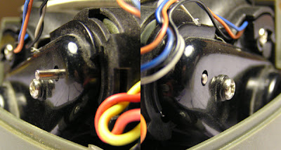
You can see in the photo that the shaft on the new motor is a bit longer than the old one. This doesn't seem to interfere with anything. I could cut it down, but I didn't want to risk getting metal shavings all over the motor, they can be a bit of a pain to clean off the magnets.
I shelved the unit for another year or so, and just now I'm getting around to doing something with it. I've disassembled it again and pulled the main board out.

Getting the mainboard out wasn't difficult. I took pictures of all the wire connectors so I could replace them properly later, then pried it out using the screw holes:

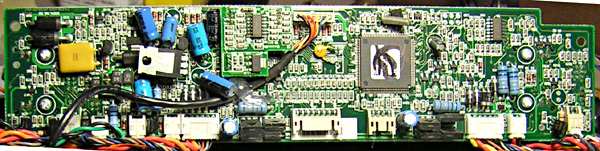
I found that the H-bridge's for the drive wheels are built with B772 and D882 complimentary PNP/NPN power transistors. Interestingly, not MOSFETs, which is what I expected. Here are the specs:
They are the four black bits:

I found the following note on a site documenting the Discovery model's diagnostic tests:
More later as the repair (attempt) progresses.
Update: Looks like Digikey carries the transistors for about $1.50 a pair:
D882 : Product PDF
B772 : Product PDF
I'll first do some more tests to confirm that these are the problem, then I'll see if I can find some more junk that I don't really need in order to get up to the $20 minimum order. I do need some beefy diodes to build a couple of battery desulfators and just to keep around for experimentation (I've been playing with a buck-boost circuit and a blocking oscillator and I need some bigger diodes).
Update - 2008-09-22
I received an order with 4 each of the transistors above:

As you can see, the appearance matches. Hopefully swapping them out will fix the problem. I don't actually have any evidence that the components on the main board have failed, but what the heck, for a buck fifty it can't hurt to replace them. If it doesn't work I'll trace back up the circuit path a bit and see if maybe the driver for this transistor is having problems.
You can see in the photo that the shaft on the new motor is a bit longer than the old one. This doesn't seem to interfere with anything. I could cut it down, but I didn't want to risk getting metal shavings all over the motor, they can be a bit of a pain to clean off the magnets.
I shelved the unit for another year or so, and just now I'm getting around to doing something with it. I've disassembled it again and pulled the main board out.
Getting the mainboard out wasn't difficult. I took pictures of all the wire connectors so I could replace them properly later, then pried it out using the screw holes:
I found that the H-bridge's for the drive wheels are built with B772 and D882 complimentary PNP/NPN power transistors. Interestingly, not MOSFETs, which is what I expected. Here are the specs:
- PC: 10W
- IC: 3A
- BVCEO: ≥30V
- BVCBO: ≥40V
- BVEBO: ≥6V
- VCES: ≤0.6V
They are the four black bits:
I found the following note on a site documenting the Discovery model's diagnostic tests:
In prior drive-wheel-tests, the wheel-assemblies have been verified to contain functional motors, functional gear-sets, and intact drive-belts; and their 'forward-paths' through their electronic-driver circuits (a.k.a., "H- bridges" -- one per wheel) have been verified operational. The only thing new for Test-9.a to check, is the 'reverse-path' through each H-bridge. If both wheels drive the robot in reverse, the circuit is validated. If a wheel fails to rotate, it means there is a fault on the main-PWB. Often, the failed part is a power transistor -- which a small percentage of owners have been able to diagnose and replace. Most everyone else, must depend on getting another Roomba!It sounds as if these transistors are known to go out. In my limited experience, the behavior of my Roomby indicates that a drive transistor is out. If it does turn out that this is the problem, here's hoping I can be one of the small percentage mentioned above. If not, I'll spring for a $25 replacement mainboard rather than a whole new roomba. I sure hope screwing with replacing the motor hasn't dorked it up too badly, in that case I'd have to track down a genuine Roomba wheel motor, which could be pretty pricy. I'm hoping that since it has the encoder any reasonable motor should be fine.
More later as the repair (attempt) progresses.
Update: Looks like Digikey carries the transistors for about $1.50 a pair:
D882 : Product PDF
B772 : Product PDF
I'll first do some more tests to confirm that these are the problem, then I'll see if I can find some more junk that I don't really need in order to get up to the $20 minimum order. I do need some beefy diodes to build a couple of battery desulfators and just to keep around for experimentation (I've been playing with a buck-boost circuit and a blocking oscillator and I need some bigger diodes).
Update - 2008-09-22
I received an order with 4 each of the transistors above:
As you can see, the appearance matches. Hopefully swapping them out will fix the problem. I don't actually have any evidence that the components on the main board have failed, but what the heck, for a buck fifty it can't hurt to replace them. If it doesn't work I'll trace back up the circuit path a bit and see if maybe the driver for this transistor is having problems.
1 comment:
Hi David,
An ohmmeter check on the transistors should give you a quick answer on their condition. My experience with power drivers like these has been that they will have cracks in the case when they (literally) blew up. They'll usually show open circuit with the ohmmeter, tho best check is to remove them from the circuit to avoid false readings caused by the drivers to these boys.
Post a Comment